Navigation : Home : FoveaPro : FoveaPro Tutorial : Part 17
Image Analysis Cookbook 6.0: Part 17
5.C.2. Using markers to select objects
The conventional Boolean AND operation works on individual pixels. Unlike the conventional pixel-based logic, the method used in step F of the preceding example selects entire features in one image based on markers in a second image. In this procedure, using the IP•Math–>Select Features by 2nd plug-in, the order of images is important, unlike the conventional pixel-based Boolean operators, which commute (A AND B = B AND A). The use of markers in one image to select features in another is a very powerful and general tool. In the example, only those red features that contain a dark marker are selected. Note the difference between the marker selection result (red features that contain dark markers) and the conventional AND (dark markers that lie within red features) result.
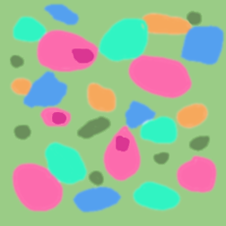
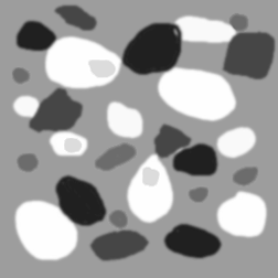
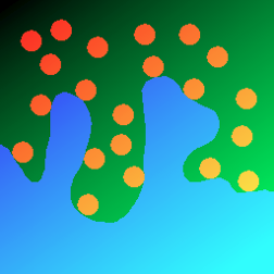
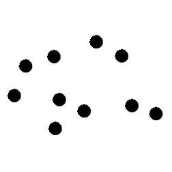
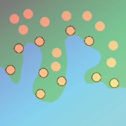
Original ColrMark image Red Channel
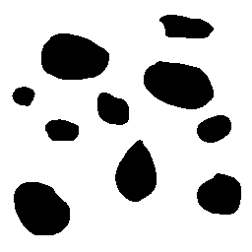
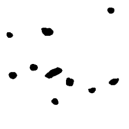
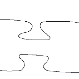
Red features Dark marks
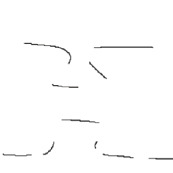
Feature selection result Pixel-AND result
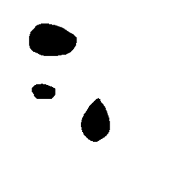
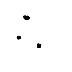
Another important application for marker selection logic is implementing the stereological disector. This technique compares serial section images to count the features that appear in one image but are absent from the second. Those “events” represent bottoms of features, by which they can be counted. The number of events (unmatched features) divided by the product of the image area and the spacing between the sections (the volume examined) gives the number of features per unit volume directly.
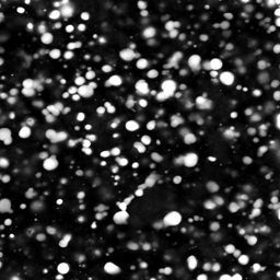
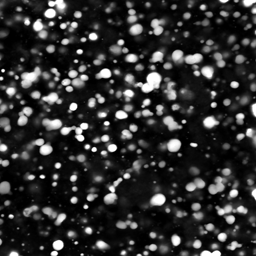
Layers 1 and 3 from Confocal
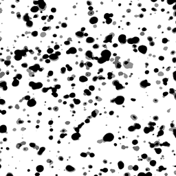
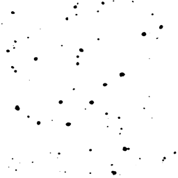
Overlay of the thresholded images with transparency showing the matched and unmatched features, and the result of using Layer 1 as a marker to select unmatched features in Layer 3 (Count = 74).
This comparison cannot be done using pixel-based Boolean logic, because the sections will not be the same size and shape in the two layer images. Marker-based selection has been used in the previous examples to find the features that are matched in two images, but now we must find those that are unmatched. This is easily done by swapping the foreground/background colors. The IP•Math –> Select Features by 2nd routine colors matched features in the foreground color and unmatched ones in the background color set in the Photoshop tools palette. If the foreground color is set to white, and the background to black, the matched features are erased and the unmatched ones kept so that they can be counted, as shown in the example. (Note - counting the features requires re-setting the foreground color to black, since the IP•Measure Features->Count routine counts features in the current pencolor. There are Photoshop shortcuts to set colors: press D for black and white, X to reverse them.)
5.C.3. Region outlines as selection criteria
Outlines and boundaries are important markers to measure adjacency (common boundaries between features) or to select adjacent features. The outlines are those pixels within features that touch a white (background) pixel. They are generated by the IP•Morphology–>Outlines function and are equivalent to performing an Ex-OR between the original image and the result of an erosion.
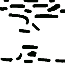
In the first example, the line of pixels immediately outside the pink substrate region can be produced either by dilation and Ex-OR or by inverting and outlining. Combining this test line or “probe” with the thresholded green features using a Boolean AND produces line segments. The ratio of the total length of the line segments to the total length of the original outline measures the fraction of the surface of the substrate that is in contact with the green features. In a multi-component structure, the adjacency of each component or phase to each of the others (many of which may be zero for regions that are not in contact) can be measured by ANDing the (dilated) boundaries around each phase and measuring the lengths to calculate the fraction for each pair.
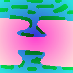
Original Adjacent image Thresholded green features
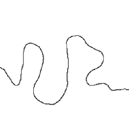
Line of pixels adjacent to pink substrate AND produces contact line segments
The next example initially looks like the same problem, but instead of a pixel-based AND, the marker selection routine is used to select the entire features that are in contact with the substrate so that they can be measured. The outline is placed in the 2nd image and used to select features that touch. Varying the amount of dilation applied to the outline of the substrate controls the definition of “touching.” The outlines of the final selected features were overlaid on the original image as a visual check on the result.
Original Touching image Line of pixels adjacent to substrate

Thresholded features Feature selection result
Visual check on the selected touching features