Navigation : Home : FoveaPro : FoveaPro Tutorial : Part 1
Image Analysis Cookbook 6.0: Part 1
0. Introduction
The process of image analysis - obtaining meaningful qualitative and quantitative information from images - typically requires several steps performed in sequence. Many software programs contain the basic tools, but Fovea Pro and The Image Processing Tool Kit have been designed to provide a comprehensive set of algorithms in the form of plug-ins that can be used with a variety of programs, ranging from the inexpensive (Paint Shop Pro) to professional (Image Pro Plus). They are particularly effective when used with Adobe Photoshop, because of its ability to handle 8 and 16 bit per channel images, display images in layers, and manage color spaces. Also, Photoshop provides a well documented and familiar environment for many users, supports a variety of file formats, acquires images from many diverse sources (cameras, scanners, etc.) and manages color printers. This tutorial will assume a basic level of familiarity with Photoshop. Books such as David Blatner and Bruce Fraser “Real World Photoshop” (Peachpit Press, isbn 0-321-24578-4 ) provide excellent guides to the effective use of the program, supplementing the program’s own documentation and help files. For a deeper explanation of how the various plug-in algorithms function, refer to John Russ “The Image Processing Handbook,” 4th edition, CRC Press, Boca Raton FL, 2002 (isbn 0-8493-1142-X). A more detailed guide to stereological measurements can be found in Russ and Dehoff, “Practical Stereology,” 2nd edition, Plenum Press, New York NY (isbn 0-306-46476-4).
The following roadmap offers a condensed guide to the most common procedures used in processing and measuring images. In the great majority of typical situations, this tutorial will cover the required steps. Follow this guide in order, selecting only those steps that apply to your particular images. For instance, for a grey scale image you would skip the steps that pertain to color images, but procedures to reduce image noise would be performed before edge enhancement; for images with good, uniform contrast you can skip steps that correct nonuniform illumination, adjust contrast, or increase local contrast, etc. For each topic, examples are shown that will help explain the procedures and show results on a wide variety of images. These examples do not exhaustively cover the various plug-ins or their options. The second part of the documentation is organized by menu and plug-in, and is a more traditional manual on the use of the software. The emphasis in this tutorial is on when and why to apply various techniques to images, to teach how to perform the various steps involved. Actual hands-on practice is essential for learning to effectively utilize the software tools. The possibilities illustrated for processing and measuring images will help you to plan procedures for your own work.
1. The program environment
This is not intended as a tutorial on Photoshop, nor a comprehensive guide to cameras and scanners, but a few reminders may be helpful. Obviously, it is important to acquire the highest quality original images. The selection of the type of camera (color, monochrome, video, digital, tube-type, CCD, CMOS, etc.) or scanner (single pass, three pass, bit depth, reflective or transparency, etc.) influences the need for processing the resulting images, because of the characteristic types of artefacts that each produces (noise - both periodic and random, real resolution as opposed to the number of stored pixels, color response, linearity, shading, etc.). Once acquired, images are stored in files, and many different formats are available. TIFF files are usually a good choice on most computer platforms and are read by most software packages. PSD is also cross-platform and accommodates text and drawing layers, as well as Photoshop’s adjustment layers. Avoid absolutely (!) any type of lossy compression (JPEG, wavelet, fractal) since you cannot be sure what information will be lost or changed that might be important in subsequent analysis.
If you are not aware of the damage done by lossy compression, try the following: subtract an original image from the compressed version to see the change in colors, size, edge locations, and other details. Then examine the hue channel of the compressed image to see how much resolution has been lost.
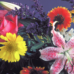
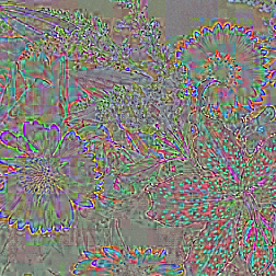
Fragment of the original Flowers image Difference between the original and JPEG version
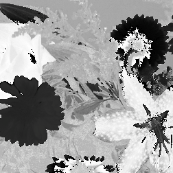
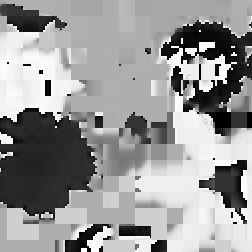
Hue channel of the original image Hue channel after JPEG compression
There are many acceptable choices for printing with dye-sub, ink jet, and laser printers. Printer type and selection of ink and paper affect the image quality and must be balanced against the uses for the prints (draft, final report, publication, poster, etc.). For correct color rendition it is essential to use ICC profiles for all output devices (the screen as well as the printer, but this is much more difficult for LCD displays than for CRTs). Calibration devices and software are available, such as the GretagMacbeth Eye-One system, that can control all of these devices. The dynamic range of prints is less than that of the screen display, which in turn is less than that of film, and of human vision. The Photoshop browser shows thumbnail images and provides a basic capability to organize folders of images, enter keywords, etc. For large image sets, the use of a database to manage the collection is important, and this is still an evolving field.
The usual image modes for processing and measurement are 8 or 16 bit per channel greyscale or RGB color. If an image has been acquired in another mode (e.g., indexed color, CMYK, etc.) you can convert the mode ( Image–>Mode ) but it may not have the full range of brightness or color information present. Imaging devices that capture more than 8 but less than 16 bits of dynamic range per channel, such as cooled cameras, produce images that are generally stored and processed as 16 bit images.
The “frontmost” or selected image window is always the one being processed or edited. Some operations require two images (e.g., subtraction). This is always done by selecting the second image (which will be used but never modified), and then choosing Filter –> IP•2nd Image –> Setup . That copies the image into memory where it will remain (unaltered) for any two-image operations until replaced. Photoshop also allows images to be layered on top of each other, and combined in various ways, but while very useful for visual comparisons, that capability is not used in the following examples.
Photoshop offers a conventional “undo” capability, but also has a history palette that provides direct access to previous states for each open image. Mastering this important tool is strongly recommended. It is also possible (in Preferences) to have the entire history saved to a text file or with the image as a way to document the procedures used.
Selection of regions within images can be used to restrict processing or measurement. Several selection tools are available. The marquee tool draws rectangular or elliptical regions, the lasso and polygon tool draw irregular shapes, and the wand tool selects regions within a brightness tolerance of the point clicked on. The shift and alt or option keys may be used to add or subtract regions. It is often useful to display the selected region as a “quickmask,” which can then be processed or edited as a greyscale or binary image. The quickmask shows the selection as an alpha channel, with 8 bit values. Some Photoshop tools (e.g., the “fuzziness” slider in the Color Selection procedure, and feathering a selection) make use of this proportional capability. The marquee outlines and plug-in routines consider a pixel “selected” if the alpha channel value is at least 128 (out of 255). It is generally safest to turn anti-aliasing off when region outlines are used to select areas of an image for processing or measurement, so that pixels are either fully selected or not.
Tools for adding text, lines and other labels are often very useful, with selection of colors, fonts, etc., as required. Keeping the text, etc., separate from the original image pixels is usually a good idea, preserving image details and also allowing for better quality graphics. The foreground and background colors can be instantly reset to black and white, respectively, by clicking on the icon in the tools palette or by pressing the “D” (default colors) key. There are many other keyboard shortcuts, and the user can define additional ones, but with a few exceptions they are not used here for clarity.
Some additional notes related to the use of Photoshop Actions for automation are collected in Section 7.
2. Correction of image defects
2.A. Color images
Many of the adjustments to color in images are performed using the built-in Photoshop tools, but a few require the more advanced algorithms of the plug-ins. It should be noted that in many cases the actual colors in images do not matter except as a way to distinguish one structure from another, and matching the appearance of the original scene, the on-screen presentation, and hardcopy printout is not required.
2.A.1. Is color correction required?
The Image–>Adjust–>Levels controls can be used to alter the contrast and brightness of the individual RGB channels, but for the greatest control it is preferable to use the Image–>Adjust–>Curves routine. This displays the curves that map the original to the processed brightness in each channel, each of which can be manipulated in detail. However, the most efficient method uses the eyedroppers by which the user can manually pick out white, black and neutral grey points in the image (assuming that such locations exist). By adjusting the proportions of red, green and blue to be equal (hence neutral greys) at those three points, the other colors in the image are usually corrected as well. In the example the black, white and grey points that were used are marked. The resulting curves are shown as well.
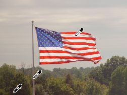
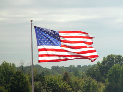
Original Flag image Color adjustment
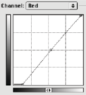
Adjustment curves for each channel.
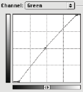
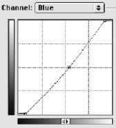
Tristimulus corrections offer a more powerful and complete way to correct colors in images by combining the values from the different channels. This generally requires measuring the RGB components in an image that contains known color panels, for example by including a color chart in the scene. The IP•Color–>Normalize Color plug-in will try to find the reddest, greenest and bluest patches in the scene (as in the example image shown), but in some cases it is necessary to place a selection on the image to locate them. The program measures the RGB components and calculates the tristimulus correction matrix, which is stored in memory. This can then be applied to the entire image, or to an entire series of images acquired with the same illumination conditions (select IP•Color–>Tristimulus Correction to apply the stored values)
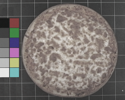
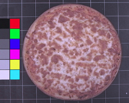
Original Pizza1 image After tristimulus correction
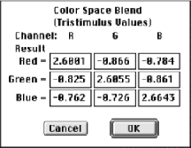
Calculated tristimulus matrix
2.A.2. Color filtering and channel separation to improve contrast
When color information is used to distinguish different structures, the application of color filters or use of individual color channels or a combination of them may improve the contrast and simplify selection. It is rarely appropriate to simply convert the image mode to greyscale. In the Photoshop Channels window, clicking on the R, G or B channel will display just that channel, and allow it to be processed as a grey scale image. You can also select Split Channels from the Channels window to replace the RGB Color image with the three separate greyscale images containing the red, green and blue channels.
The image can also be converted to Lab mode and the luminance, a and b channels accessed in the same way. The IP•Color–>Color Filter routine can be used to isolate the Hue, Saturation or Intensity channels, or to apply any color filter to the image (functionally the same as placing a filter of that color in front of the camera). Finally, the IP•Multichannel plug-ins use principal components regression to find an axis in color space along which the greatest contrast in the image results, so that the first channel shows the optimal grey scale contrast. After the color filter or PCA routines, the image is still in RGB mode and should be converted to greyscale mode to simplify and speed up further processing. The example image illustrates these color channels.
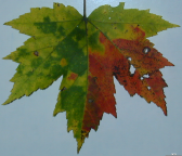
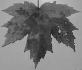
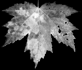
Original Leaf image, conversion from RGB to Greyscale, and Optimal Grey result
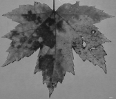
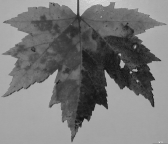
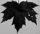
Red, Green and Blue channels
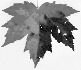
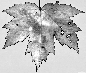
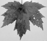
Hue, Saturation and Intensity channels
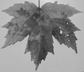
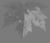
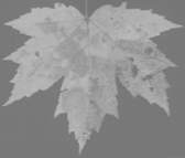
Luminance, a and b channels
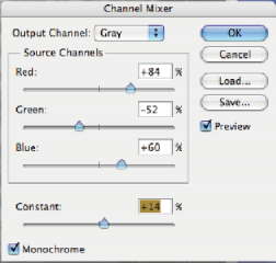
Another way to interactively combine the RGB channels to produce a grey scale result is the Layer–>New Adjustment Layer–>Channel Mixer dialog. This allows mixing together arbitrary amounts of each channel to produce a desired result.